■ Displaying 64 colors simultaneously with PC-8801 mkIIMR
The PC-8801 from SR onwards has a graphics function that displays 640x200 pixels and 8 out of 512 colors.
Since the number of colors that can be produced simultaneously is 8, it may be difficult to choose anything other than the basic 8 digital colors, and there are very few opportunities to use a DAC that can display 512 colors.
One pixel is represented by one bit of RGB each.
If we consider 2 horizontal pixels as 2 bits each for RGB, the horizontal resolution will be halved, but the color depth will be doubled, which means 320x200 pixels and 64 colors can be displayed simultaneously.
It does the same thing as the PC-8001 mkII's 640x200 monochrome ⇔ 320x200/4 color display switching function.
■ Hardware modifications
I'll look at the PC-8801mkIISR circuit diagram sideways and see if I can get my hands on it.
MR is even more highly integrated than SR, and it seems that most of the circuits related to graphics are included in a custom chip,
so I decided to insert the circuit into the 7406 x 2 part that is the entrance to the DAC.
The RGB data coming to the DAC is taken in according to the dot clock, and in 640x200 mode it is output without doing anything,
and in 320x200 mode it outputs 2 pixels at a time as 6 bits.
 On the MR motherboard, IC16 and IC20, 7406, are the input side of the DAC.
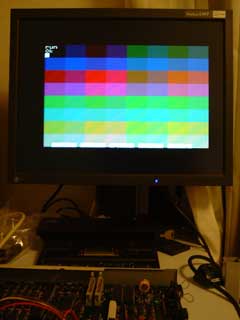
The signal coming to 7406 looked like the picture on the left.
Remove these two 7406s from their socket.
The area around the three transistors on IC16 is the dot clock distribution section, and the dot clock is taken from here, but since I didn't know which of the distributed clocks to use, I decided to use the R60 at the bottom (on one side).
 The circuit to be added consists of the XC9536 and the two removed 7406s.
The power supply unit is placed above IC16 and IC20, so there is not much room for height.
Here is the contents of XC9536.
In order to output 2 pixels together as 6 bits, it is necessary to correctly determine the boundary between each 2 pixels.
Therefore, we decided to assign all intermediate colors to the palette and detect the transition from the 8 digital colors to the intermediate color to determine that boundary.
Specifically, all green components of the palette are set to G2=0, G0=1, and R1, G1, and B1 are used as RGB components.
If G2=0, G0=1, it will be graphics, otherwise it will be the border color or text.
If the displayed content on the text screen does not match by 2 pixels horizontally, the synchronization will be lost and the display will become strange, so set the text to 40 horizontal character mode or semi-graphics mode.
An I/O port for switching between 640x200 / 320x200 modes is provided on the expansion slot and connected to additional circuits.
I don't mind a switch, but it's just a matter of taste.
■ Software
From the software side, in 320x200 / 64 color mode, each byte of each VRAM plane appears to be 4 shades x 4 pixels (2 bits x 4).
Other uses remain exactly the same. (Of course, this does not mean that we have changed the 88's graphical functions, but only the interpretation (?) of the output.)
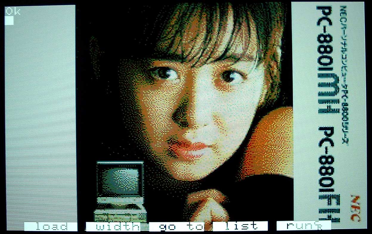
■ Sample pictures
I have a crappy digital camera, so I can't take very good pictures, but the colors are really good in real life.


■ References
- PC-8801 mkIISR complete circuit diagram
- PC-8801 mkIISR technical map (2)